When I originally started this project, I was going to take photographs every step of the way. Sorry, we got started and rarely did I think to take a photo. There are also posts on
The RV Forum Community
and on
IRV2
Started refrigerator replacement project at about 11AM.
Used the steps listed in my outline and ran into very little problem.
·
Turn off refrigerator
Turn off Propane at tank
Clean out refrigerator and freezer
Turn off refrigerator electrical breaker
Removed exterior access panel – from there -
Unplug the 120v supply
Disconnect the 12v power Supply
Disconnect Propane Line
Cap Propane line with Watts Compression fitting cap – Use Pipe Dope- Not Teflon
tape(we capped at main feed line)
Disconnect and cap water line
– leave valve in place at this time
Remove any obvious mounting/securing screws (found two on each side. Bolts that
go into captive nuts on Motorhome mounted flange.)
Remove Refrigerator Vent Cover – from roof – (My vent cover was destroyed in a
wind incident enroute to the location we were doing the swap. Held on by bungee
cord and duct tape)
Through vent, see if any securing screws are evident – (found two straps
mounted to exterior Motorhome wall and four screws into top of refrigerator)
Remove all refrigerator doors
Remove shelves, drawers and other loose parts inside refrigerator &
freezer.
Remove drawer below the refrigerator
Remove any trim pieces around and across top of refrigerator (top and bottom
trim is screwed through a flange surrounding the refrigerator into the wood
cabinetry that surrounds the refrigerator. Screws were covered with caps. Side
trim just “snapped” into the flange along the sides of the refrigerator)
Attempt to slide refrigerator out of opening -
If it moves – create platform with dolly to slide refrigerator onto -
If it does not move, look for other screws or bolts holding it in place and
polyurethane adhesive
Slide refrigerator onto dolly and move to center of living area
Remove cooling unit from back of refrigerator – Make lighter – if necessary(we
did not do this)
Carefully tip refrigerator on narrow side, slide down 2x4 ramp on entrance
stairs and out of MH (see narrative for how we removed the refrigerator from
the Motorhome)
Reassemble refrigerator, install doors, cooling unit – if removed.(We left it
in pieces)
Remove existing Refrigerator floor
Remove drawer hardware
The refrigerator was held in by two
straps on top going from the side wall to the top of the refrigerator, and held
to the top with four not very efficient screws.
From inside, at the top, against the back wall are the top
mount brackets from the factory. The white strips on the side and top is weather
stripping that we left in place.
Found the four bolts, two in each side that went through
metal plates attached to the side of the refrigerator and into metal plates
mounted to the interior wall of the Motorhome. These bolts were easy to get to.
The interior edge of the refrigerator has a flange around it that has screws
into the wood cabinetry at both the top and bottom of the refrigerator. These
screws are cover with caps. Gas line disconnected and later removed entirely.
Pushing from the back freed the refrigerator and let it slide forward. We did
find polyurethane sealant/adhesive on the bottom of the refrigerator. Dan and I
then slid it completely out and lowered onto the furniture dolly. We then moved
it into the center of the Motorhome where we then removed the steel flanges
along both sides in the back. These flanges bolted to the wall plates in the
back.


We then positioned the refrigerator in the doorway, removed it from the dolly
and laid it on its side.
The dolly was then placed under the refrigerator side toward the top. We put
the heavy end out the door first. With one person outside on the heavy end and
one person on the "light" end controlling the dolly, we were able to
"roll" the refrigerator out the door and gracefully down the steps.
Since this is a side entry Motorhome, the doorway is 27 inches wide. We did
remove the grab bar on the back side of the door and this gave us the full
width. The refrigerator with the cooling unit measures 25 inches wide at the
widest point which is where the stack is. Once out of the Motorhome Dan and I
could easily carry the refrigerator to a spot outside his fence along the street.
All on the doors that we had removed were stacked there also, and about five
hours later some people showed up and asked if they could have it. Off it went
in the back of a trailer.
With the refrigerator out we needed to remove the existing
floor and framing. The existing floor was held in place with polyurethane sealant
and two screws. The drain pan for the refrigerator was plastic mounted along
the back wall about four to six inched wide. We removed the drain pan first,
cutting it with a multi tool into sections.
Once that was removed we simple cut the floor from front to back with the multi
tool and removed it in two sections.
The floor appeared to be a piece of Motorhome side wall that was left when a
window opening was cut into a side wall during the construction. It consisted
of a piece of Luan, two inches of white open cell foam and then the exterior
filon or fiberglass.
Having removed the floor, we found that the frame work that
supported it was 3/4 x 3/4 wood strips, with a occasional 3/4 x 2 inch piece
serving as a vertical support. There was no center support structure. This kind
of gives testament to the strength of the laminated side wall, at least this
small section. We removed the frame work along the edges and some light metal
angle material that was screwed horizontally along the back wall. We then started
the removal of the cabinet framing on the inside of the motorhome. we did this
with great care as the original plan was to shorten it and reuse it. This frame
work contained the opening for the drawer, and below that the mounting area for
both an electrical outlet and the gas detector. These two items were mounted in
particle board that was stapled to a 3/4 thick frame. the material used to
create the frame was a particle type board covered with wood grain vinyl. This
was slow going as we cut through staples and carefully pried things apart so as
to not create more damage. This was very slow and in hind sight probably not
worth the effort.

The frame of rails and stiles (cabinet talk) were held to
the refrigerator side framing with some 3/4 x3/4 strips staple to the inside
frame, which was then screwed to the interior supports. The project continued
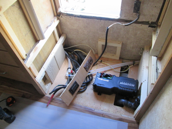
after a beer and sandwich. Since we needed to put an inverter under the
refrigerator, we needed to run two 1/0 and one #6 cable from the refrigerator
to the batteries. The easiest path was to remove the drain line and use that
hole for one cable (inside split loom) and the hole that the gas line went
through was used for one 1/0 and the #6 cable, both inside split loom. Since
the propane tank sits directly below the refrigerator it made finding and
running the wires much easier. One more hole had to be made to accommodate the
battery sensor wire for the Inverter. This did not take much as the exterior floor
is just two layers of thin metal with foam insulation in between. This sensor
cable was also placed in split loom. With that part started (wire in the split
loom and run through the floor and stretched out along the ground) we could move
to other tasks. We found that the gray water tank sits in this area, below the
refrigerator, and the area that the wiring and gas lines penetrate the exterior
floor is beside the tank. Care was needed to make sure that any holes that had
anything put in from the top did not penetrate the tank. The sub-floor is ½
plywood with 2 inch white open cell foam (foam is easily pulled apart) with
another layer of plywood underneath. Dan
had started on the design for the new floor. We decided to use 2x2 material for the frame.
This was easy to source (big box store) and to work with. It was off to the
store for supplies and the end of day one.
Day two found us starting out with the layout of the frame for the refrigerator
floor. First thing we needed to do was lower the vent stack of the grey water
tank.
We purchased a female threaded collar and cut the existing vent stack off to
about an inch above the fitting into the tee. We glued the collar on above the
Tee and then threaded the vent fitting onto the Tee. This lowered the stack
about three inches. Since the vent cap has a one-way valve it in, hopefully we
will not get any water (or fumes) splashing out as we drive down the road. We
had looked at alternate routing locations, but could not find one that would
work.

Since we decide to use 2x2 material, that was easy to handle, a small 4.5 inch
circular saw was used, (Compound Miter saw would have been better) to cut a
series of 6 1/4 inch uprights. We then measured for our front to back
stringers. We glued the uprights and put them between a top and bottom
stringer, screwing them through both top and bottom stringers. We then took
some 1/2 inch plywood and made a gusset that we then attached to the upright
and the top and bottom stringers, with 1 ¼ 18ga brads, like making a truss. We
then anchored the bottom stringer to the subfloor with glue and screws. The end
frames we also anchored to the sidewalls.
We built a small center frame that we attached to the outside wall of the Motorhome.
We then located the UPS unit where we wanted it and anchored with some 3/4 x 1
lag screws. Then a diagonal frame was built that goes from the rear right
corner to the left front corner. This gave us the center support. A front
stringer was made with a 2 x 4 flat and using three 2 x 4 uprights. This gave
us the front support, a little stronger than the 2 x 2 stringers. We positioned
the uprights in a fashion to give an opening about 9 1/4 x 16 for access to the
outlets and the inverter. The battery cabling was run for the inverter.


We were fortunate that we were able to follow an existing wiring bundle back to
the battery cabinet. Not that this was without a little difficulty, but much
easier than we had envisioned when we first looked at the problem. To get past
the axle, I ran a fiberglass wire fish rod along the existing wire bundle,
connected the cable and pulled it through. For the refrigerator floor, a piece
of 3/4 plywood was sourced and a trial fit was made. The initial cut was made
with the width of the opening, about 34 inches x 25 inches deep. This put the front
edge of the floor right at the edge of the cabinetry. That ended the second day
of construction.
On day three we decided to add a gusset to the frame
against the outside wall. Again we used a piece of 1/2 inch plywood. Metal
angle braces, metal "T" braces and metal corner braces were added in
various locations on the frame work to give the frame more structural rigidity.
Connections were made to the Inverter using end connectors that are held to the
wire with set screws. These connectors were then well taped with the proper
color tape to show polarity. We used 1/0 for both the positive and negative
lines and #6 for the frame ground.

All three were flexible welding cable which made working with it much easier.
Connections at the battery were made using the same type of connector. The
positive cable goes through a 200 Amp T Class fuse (this was later changed to a 150 Amp T Class fuse) in a holder that includes a
clear plastic cover. The cable is held to the fuse with set screws. A ground
wire connector, normally seen in a home circuit breaker panel was used to make
the frame ground connection. The remote for the Inverter was mounted in the
wall to the right of the microwave. Not a great location as you cannot get
directly in front of it, but a usable location. Once the hole was cut, since we
had access to the back side, two furring strips were added for the mount screws
to penetrate.

The remote cable was shortened to the proper length so that 30 feet of wire did
not have to be stuffed between the wall and the refrigerator. With the Inverter
in place and connected to power, it was load tested with a small vacuum cleaner
and it worked perfectly. The floor was then trimmed and notched in the back to
accept the refrigerator power plug. With these things done, it was wait for the
refrigerator which is scheduled for Tuesday.
Day four was a day of frustration. The Home Depot crew
(actually GE) delivered the refrigerator at about 10:45. As soon as they saw it
was going into a Motorhome, they stated no way. They stated that it was
considered a liability issue. If they delivered it into the Motorhome and the
refrigerator fell over damaging property or people that they could be sued. An
offer of $20 ea did not work. So after unboxing the refrigerator and confirming
no exterior damage - off they went leaving the refrigerator sitting next to the
Motorhome. The next 45 minutes was spent taking the doors off the refrigerator,
removing the freezer drawer/door and other items, like the trim over the
levelling feet on the front and the bracket to hold the levelling foot. Then
Dan and I and a couple of his friends hoisted the refrigerator into the
Motorhome. This refrigerator is a little heavier than the Norcold, but not by
much. Once inside we put it on a furniture dolly and moved it into position in
front of the opening. We did not build up the level of the furniture dolly to
the same as the refrigerator opening, and that would have helped. So, we lifted
it into the opening and pushed it back into place, tight against the back wall
and the next frustration happened. Though the refrigerator is only 24 inches
deep, for it to sit properly on the floor, the floor needs to be deeper than 25
inches, which is what we built. The wheels on the refrigerator were on the edge
of the floor, I mean inhale deeply and the wheels would roll off the edge of
the floor causing the refrigerator to tilt forward.


So, the question got to be what can we do to resolve the problem. The ideas
ranged from adding another 1.5 inches on front of the floor and opening with a
2x4, to building a bracket to hold the refrigerator in place anchored to our
existing frame, removing the wheels somehow and hope that the bottom of the
refrigerator would support the weight, but still leave ventilation, to cutting
a new piece of floor that would extend past the front of the refrigerator
enough for the leveling feet to sit on it. Anchoring the refrigerator was also
part of the discussion. Long story short, we removed the refrigerator and cut
another piece of 3/4 inch plywood. This time we cut it at 29 inches deep, about
four inches deeper than the first one. This gave us ample room to place the
refrigerator, and set it a couple inches away from the exterior wall.


Once we had the new floor piece cut and set in place, we positioned the
refrigerator on the new floor, and marked where the front levelling feet would
set, except we had removed the foot and would drill a hole in the floor to
accept a bolt. We also marked three locations through the exterior refrigerator
door where we could place bolts to anchor the refrigerator to the floor. These
locations through the base of the refrigerator were near the center and left
side (looking at the refrigerator from the front) of the refrigerator. There
was no way to reach to the right side (again looking at from the front) to mark
any holes.


The holes through the plywood where the leveling feet reside was reinforced
with an 18-inch piece of predrilled steel 1/16 thick strap. This was anchored at
four points with 3/8 by 1 1/2 inch lag screws. The intent was to reinforce the
hole in the plywood should the refrigerator try and slide forward into the
Motorhome. The refrigerator was put back into place and it was anchored through
the floor both front and back using the holes that we had drilled. Through the
holes we used 5/16 diameter bolts with fender washers and nylock nuts. We found
that since the power cord came from the top of the refrigerator we were short
about 2 inches of reaching the outlet under the floor. This was solved with a
short extension cord. The shelves were replaced into the refrigerator, it is a
good thing to do this prior to replacing the doors, as the doors might not open
enough to get the shelves in. The doors were installed, though there is little
clearance once the refrigerator is installed, it is doable. The freezer drawer
was assembled, the baskets lift out and the door comes off the rails. The unit
was plugged in and seems to function properly.

Day five we woke to a nice cold refrigerator (38 degrees)
and a chilly freezer (-2 degrees). Today we reviewed our anchoring system and
decided to add two blocks, one on each side of the exterior access door, to
keep the refrigerator from sliding backwards. We also installed three straps to
the top of the refrigerator. Coming from the factory installed anchor point,
one strap was placed to both front corners and anchored to the top of the
refrigerator using the screws that hold the top control panel in place.
A third strap connects from the factory anchor to the top of the refrigerator
in the rear (left) side, toward the inside of the Motorhome. Two self tapping
#8 by 3/4 were used.
Spacers will be added under the leveling foot bracket - right now it is just a
5/16th bolt going through the foot and through the plywood, with a fender
washer and nylock nut on the bottom. Nothing really for the bracket to sit on. Door latches were also added to the
refrigerator. Don’t want the doors flying open as you drive down the road. We
used “Lamp Locks,” these are the same used by several RV Manufacturers. We
placed one in the center of the door handles to hold the two doors together.
Another was placed on the left door connected to the
freezer drawer. We contemplated putting it on the side of the freezer door to
the frame, but I was concerned with it getting in the way of the drawer to
frame seal.
I used 3M mounting tape – the 85 pound variety. The doors
stayed closed on our 800+ mile trip home.
The final step in this process will be to finish out the opening below the
refrigerator. Across the top and down the sides.
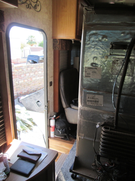
So, from this:
To this, in five days –
To complete this saga,
we will start with a few things we found on the trip home from Arizona where we
installed the refrigerator.
First thing we found was
that we the shelves in the refrigerator were not in the proper location. An
easy fix, until you realize that the shelves are easily adjusted if you can
get the refrigerator doors open to a complete 180-degree angle. Well, guess what,
the left door will come close, but there is no way the right door will open
that wide. So, off with the right door so you can get the shelf in the proper
place.
The next thing we found
was that this make/model of refrigerator does not have an on/off switch. Once
you plug it in it is on. I thought that the outlet that I was using for the A/C
power to the refrigerator (Inverter 120v inbound) was a dedicated circuit. It
is a dedicated circuit, but it has both the refrigerator and the
Converter/Charger on it. So, I could turn off the circuit and shut off the
refrigerator, but would lose the charging of the batteries when the unit was
plugged into 120v power in storage. I thought about using the charger in the
Inverter to charge the batteries but then the trickle charge to the chassis batteries did not work. It would also cause a situation where if the A/C power went
out, when it was restored the Inverter would come on and the refrigerator would
come on. So, I opted to put a switch on the A/C out of the Inverter. Now, I
just turn the switch on above the Inverter control panel when I want the
refrigerator and turn the switch off when we park the Motor Home in storage. These
items were very minor and both could have been avoided with a little more
pre-planning.
The next part was to do
something with the space under the refrigerator and to the platform that
extends out underneath it.
Filling the space
underneath was relatively easy. I already had a design in mind on how to
accomplish this. It did change a little, but not a lot. I knew that I needed to
have access to the Inverter, so that meant a door of some sort. I knew that I
had the propane detector and an electrical outlet to mount. I envisioned a
frame that had a panel on one side for the electrical outlet and the propane
detector and the other larger side would have a door that could either be
opened or removed to service the UPS.

I envisioned using the
solid maple drawer front that I had removed as the door. I could try and stain
wood frame as closely as possible to the existing frame work. I started by
building the frame. I had taken measurements and drawn a diagram, but the work
got slowed because I did not have access to the motor home to test fit the
frame, as it was in the shop awaiting parts and repairs. The motor home had
been damaged by a wind event on our way to Arizona. This incident has been
posted in on-line RV forums and discussed and dissected to death. For the frame,
I used 11/2x3/4 Ash wood imported from New Zealand (available at Home Depot). I
used a piece of ¼ plywood for the panel to hold the electrical outlet and the
propane detector. (Propane Detector was replaced as the original one is about
eight (8) years old.) This left a decent sized opening in which to get to the
main items on the Inverter if necessary. Then I started on the door to cover
the opening and things ground to a halt. I could not in good conscious cut that
20x14 piece of solid maple down to 7x18. It is much too nice to do that.

So, I built another frame from wood, slightly larger than my opening. Some
stamped aluminum vent material was obtained to go on the back of the just
competed frame. When in place it looks like the cover over the HVAC
filter/return air, just smaller. It will also provide more ventilation for the
Inverter.
This cover will be held
in place with latches that have a diamond shaped protrusion on one piece and a
unit with double rollers on the other stationary side. The post goes on the
back side of the cover and the double roller mount on the edges of the opening.
When you put the cover on the posts go into the double roller. The main frame
is anchored with screws into the refrigerator floor framing. Only two screws
are visible and those are covered with wooden “buttons” that are stained the
same color as the rest of the wood.
The next part was the floor that the refrigerator sits on, specifically
the part that comes out past the wall cabinetry.

Since we were not able to turn the leveler feet brackets inward and
still use them as an attachment point for anchoring, they protrude out from the
refrigerator a little. With the factory cover on, they stick out just slightly
passed the closed doors of the refrigerator. One of the things that I did was
to cut some circular pieces of wood the same diameter as the leveling feet for
spacers. I then ran the anchor bolt through the floor, through the spacer then
through the leveler bracket and put a nylock nut on. When I tighten this bolt,
it gives the refrigerator something to “sit” on other than air. For safety sake, the bolt goes down from the
top with the nut on the bottom, so if the nut comes off at least the bolt is
still in place to provide a little level of security in keeping the
refrigerator from moving. I then traced around the bottom of the refrigerator
in the front and using a combination of a scroll (saber) saw and a vibrating
multi-tool, cut that shape into the plywood floor. After some sanding, I
painted all the expose plywood of the refrigerator floor black. Once the
factory cover is in place, the floor is not that noticeable.


Next came closing the two
(2) inch gap at the top of the refrigerator. I had kept the black trim that was
around the Norcold and tried to envision a way to use it in conjunction with
something else to cover or close the gap. I ended up using garage door seal
that is intended to go on the bottom of the garage door. It is about 3 inches
wide and has a rib on the top and bottom that is about ¼ inch wide. I cut the
rib off one side, and then used the trim piece from the original refrigerator
to hold it in place.
I may try and use a
vertical strip also from the original refrigerator to go down along the
refrigerator. It was attached to a flange on the refrigerator and probably will
need to be glued in place.
The refrigerator is the Samsung RF18, a counter depth model. It draws about 2 Amps A/C, but draws about 18 Amps D/C when on the Inverter. The Inverter is powered by the House batteries, three (3) 12v 160 AH batteries. I estimate that we should have about 12 hours of run-time on the refrigerator, using the Inverter, before we will need to recharge the batteries. All in all I think that it is a great modification. With glass shelves, we are using non-skid material under pans and glass containers. In addition we also added the double refrigerator retaining rods to keep things on the shelf when traveling. The next project is to install an Automatic Generator Start (AGS) so that if we are boondocking if the batteries get to low, the generator will start and charge the batteries.